You want to read more blogposts about UHPC?
10.12.2020
CRC in actual fires - Full scale testing on simply supported slab
It is not often that I get to see the results of full-scale fire testing on UHPC elements – so the least I can do is to share some results from a recent test on a simply supported slab for those of you that are interested.
Fire resistance is certainly a challenge for UHPC – and I have addressed this in one of my earlier blog entries: Fire resistance – is it a problem for UHPC? If contents of fine particles in the concretes are high (leading to relatively impermeable concretes) it can even be a problem at compressive strengths as low as 55 MPa as addressed in the Eurocode system.
As described in my earlier post we have achieved extensive documentation regarding spalling and fire resistance – including tests on slabs, beams, columns and wall elements – but only one full-scale test under fire loading has been carried out on a balcony element. This was a cantilevered balcony element that was tested at Tampere University in Finland (the set-up is shown in fig.1 below).

Figure 1. A cantilevered CRC balcony slab installed in the furnace prior to testing.
While the cantilevered balconies represent the majority of our balcony projects we decided to also perform a full-scale test on a simply supported slab as we could expect less favourable results for this type of test – as I will explain in the following:
1. Heating of reinforcement
In both types of fire test the top of the slab was unexposed, while the bottom of the slab was exposed to a standard fire. This means that the tensile rebars in the cantilevered slab are relatively well protected from the fire – as they have a 15 mm cover from the top of the slab and the slab had a thickness from 85 to 75 mm. For the simply supported slab the tensile rebars are on the bottom and thus only protected from the fire by their 15 mm cover layer. This will of course result in a more rapid heating of the rebars for the simply supported slab and thus a decrease in strength at an earlier phase of the fire test.
2. Deformations
For both types of slabs, the loading is placed on top of the slab leading to deflections downwards. As the slabs are heated these deformations will increase due to reductions in Young’s modulus for both steel and concrete as well as thermal creep. There is, however, another effect that has to be taken into account. As the bottom part of the slab is heated while the top part is relatively cold, the bottom will expand rapidly while the top is relatively undisturbed. This adds a curling effect, which in the case of the cantilevered balcony will cause the edge of the slab to go upwards – and in the early stages of the fire this effect will add a larger component than the downward deflection caused by the loading. In fact – for the cantilevered slab the edge of the balcony did not move down past the initial deflection until after 90 minutes of fire exposure. For the simply supported slab the effect of loading and of differential heating will both add to the downward deflection, so that the deflection in the middle of the slab can become quite large.
3. Spalling
If moisture content in CRC is sufficiently low we will typically not experience explosive spalling, but some spalling of the cover layer on the exposed side can be expected. Below is shown a picture of the cantilevered slab after 2 hours of fire exposure.
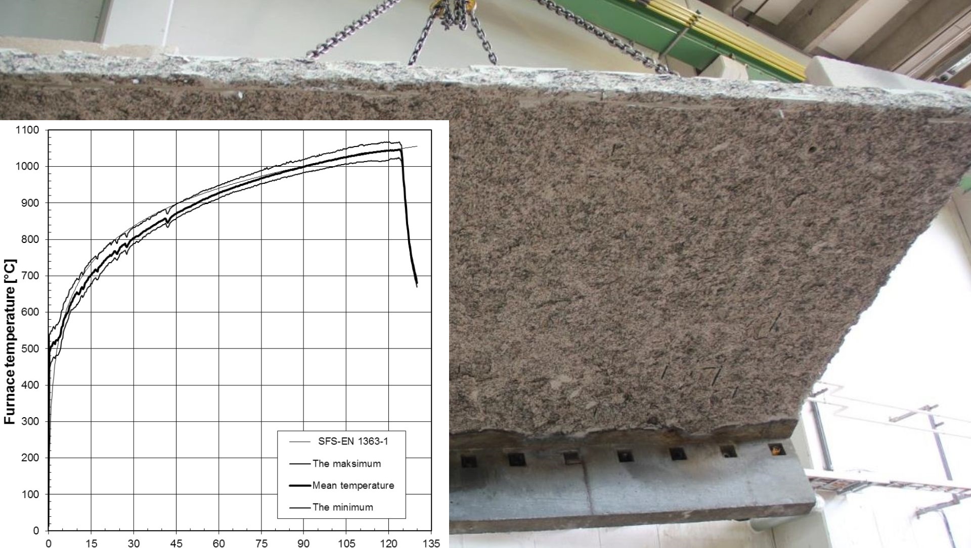
Figure 2. Cantilevered slab after the test.
For the cantilevered slab this spalling is again away from the surface closest to the tensile reinforcement, so spalling will not lead to a rapid increase in rebar temperature.
For the simply supported slab any spalling will be from the surface close to the tensile reinforcement leading to a rapid increase in temperature and subsequent loss in tensile capacity of the rebars. For an unloaded test specimen, the spalling is expected to be moderate – as has been observed in a couple of actual fires (CRC in actual fires Part 1 & Part 2) – but because of the large deformations the cover was also subjected to relatively large tensile stresses that increased the risk of spalling of the cover layer.
Fig.3 shows a picture taken after the test of the simply supported slab – and as shown pretty much the full 15 mm of cover has spalled away. Fig. 4 shows 3 cylinders that were also placed - without loading - in the furnace during the test (and until the furnace was opened the day after when it had cooled off). The cylinders had a lot of cracks, but only minor spalling and the residual compressive strength when tested after a few weeks was from 12 to 15 MPa.

Figure 3. Exposed side of slab after the test.

Figure 4 Cylinders after fire exposure and before testing.
Test results
As listed above there were a number of reasons why we could expect a poorer behaviour for the simply supported slab compared to the cantilevered slab. The cantilevered slab had supported the full load for 2 hours of fire exposure. When the test was stopped it was because the test set-up was not able to handle the deformations.
The simply supported slab was tested at the Danish Institute of Fire and Security Technology – and we did obtain an REI60 classification.
The slab had a thickness of 100 mm, a span of 4140 mm and a width of 3000 mm with a free edge at both sides. The slab was loaded in two points as shown in fig. 5 with a total applied load of 31 kN. Taking dead load into account this results in a maximum moment of 5.89 kNm/m and a maximum shear force of 5.69 kN/m.

Figure 5. Loading arrangement on top of the slab.
We had not anticipated that the deformations would be quite as large as they turned out to be, so the loading arrangement was not really suited to the large deflections. As the slab curved, tension was built up under the loading points and as these stresses were released a few times during the test, the slab almost “jumped”. In the end the test was stopped – after one hour – as the deflections became so large (233 mm center deflection) that the loading could no longer be applied to the slab. This was a similar situation to the cantilevered slab – that the slab was largely intact, but the set-up could no longer handle the large deflections even though the failure criteria based on the deflections had not yet been met. A picture taken at the 60-minute point of the test is shown in picture 6, where the large deflection – and a pool of water – can be observed. The maximum average temperature rise on the unexposed side of the slab was 64 0C and the water content of the slab at the time of exposure was 1.6%.
A lot of thermocouples were embedded in the slab so we again achieved a lot of information to improve our fire design – which is equally as important as the classification of the slab we achieved for documentation purposes. However, we still have some difficulties – especially in predicting deformations accurately (which admittedly is not so easy because of the many factors – including spalling – that affect this) so if any of you have questions, comments or information that you would like to share please leave a comment below.
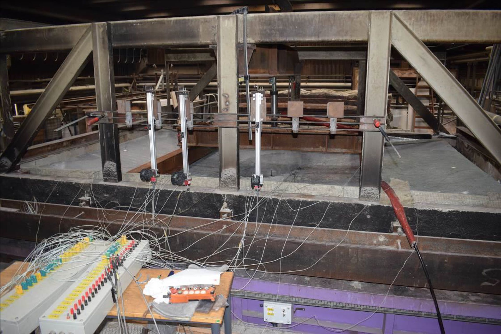
Figure 6. Unexposed side of slab 60 minutes into the test. The test was stopped at 63 minutes.